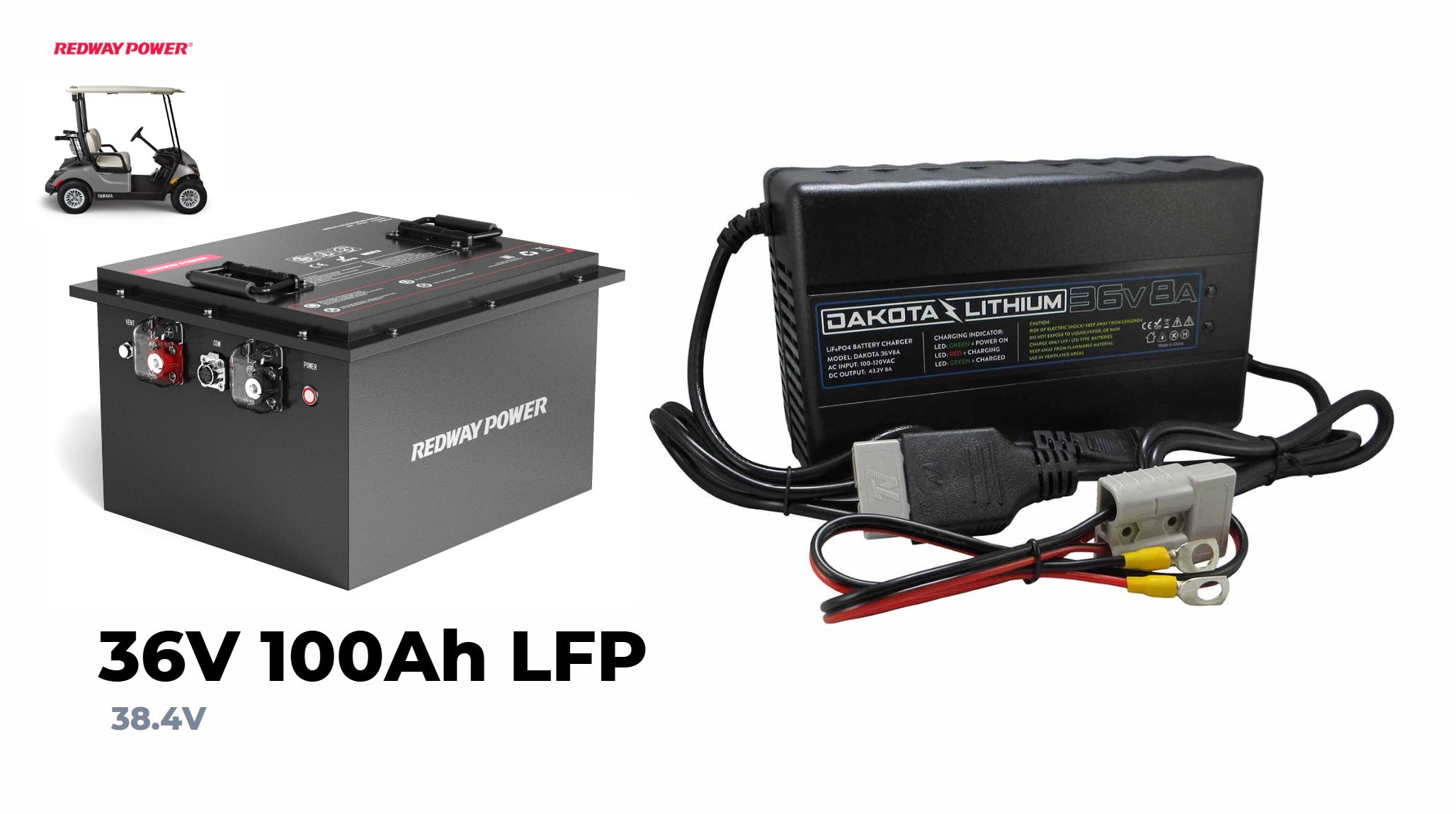
A 36-volt battery charger is designed for charging batteries configured in a 36V system, typically three 12V batteries in series. It provides the necessary voltage and current to recharge these batteries efficiently while preventing overcharging through built-in safety features.
Building a 36-volt battery charger requires a comprehensive understanding of both electronic components and the principles of electricity. A 36-volt battery pack, typically used in electric bikes, scooters, and golf carts, consists of multiple cells arranged in series. To safely and effectively charge this battery pack, we must design a charger capable of delivering the correct voltage and current. This involves selecting appropriate components, configuring the circuitry, and implementing safety features to protect the battery from overcharging and damage.
Key Components Needed for a 36 Volt Battery Charger
To construct a high-quality 36-volt battery charger, the following components are essential:
- Transformer: Converts AC mains voltage to a lower AC voltage suitable for rectification.
- Rectifier: Converts AC to DC. A bridge rectifier is typically used for its efficiency.
- Capacitors: Smooth out the DC voltage, reducing ripple.
- Voltage Regulator: Ensures a stable output voltage.
- Current Limiter: Prevents the battery from being charged with excessive current.
- Heat Sink: Dissipates heat generated by the components.
- Charging Control Circuit: Manages the charging process, ensuring safe operation.
- Connectors and Enclosure: Provide safe connections and housing for the charger.
Designing the Circuit: Step-by-Step Guide
1. Transformer Selection and Configuration
The transformer is the heart of the charger, stepping down the high AC voltage to a lower level. For a 36-volt system, a transformer with a secondary voltage around 40-42 volts AC is ideal, considering the voltage drop across diodes and the need to fully charge the battery pack.
Calculation Example:
If the AC mains is 220V, and we need a DC output of around 42V, the transformer should have a turns ratio that steps down the voltage from 220V to approximately 30V AC (RMS). Given the rectification and smoothing process, the peak DC voltage will be around 1.4 times the RMS AC voltage, accounting for diode losses.
2. Rectification and Smoothing
Using a bridge rectifier, the AC voltage from the transformer is converted into DC. The bridge rectifier configuration consists of four diodes arranged to provide full-wave rectification, which doubles the frequency of the output ripple compared to half-wave rectification and improves efficiency.
Capacitors are then employed to smooth the rectified DC. The value of the capacitors should be chosen based on the desired ripple voltage and the load current. For a steady output, a capacitor with a value of at least 4700µF is recommended.
3. Voltage Regulation and Current Limiting
A voltage regulator circuit is crucial for maintaining a constant output voltage. For a 36V battery pack, a regulator that can deliver a stable output around 42V is required. An adjustable regulator, such as the LM338, can be fine-tuned to the desired voltage.
Current limiting can be achieved using a series resistor or an active current limiter circuit. This step is vital to prevent the charger from delivering excessive current, which could damage the battery cells. The limit is typically set based on the battery’s maximum charge rate, often specified by the manufacturer.
4. Charging Control Circuit
A charging control circuit ensures that the battery is charged safely and efficiently. This circuit can include features such as automatic cutoff when the battery is fully charged, temperature monitoring, and charge rate adjustments. An integrated circuit (IC) like the BQ24450 can provide these functionalities.
Safety Considerations and Enclosure Design
Safety is paramount when designing a battery charger. This includes implementing protection against short circuits, overcharging, and overheating. Fuses and thermal switches can be used to protect the circuit and battery. A heat sink is essential for dissipating heat generated by the voltage regulator and other components.
The enclosure must be durable and well-ventilated to prevent overheating. It should also provide secure mounting for all components and sufficient insulation to prevent electrical shock.
Testing and Calibration
Before using the charger, thorough testing and calibration are necessary. Use a multimeter to verify the output voltage and current, ensuring they match the desired specifications. Test the charger with a small load before connecting it to the battery pack to confirm proper operation.
Advanced Features and Enhancements
For more advanced applications, additional features can be incorporated into the charger design:
- Microcontroller Integration: A microcontroller can offer precise control over the charging process, data logging, and user interface functionalities.
- LCD Display: Displays real-time data such as voltage, current, and charge status.
- Smart Charging Protocols: Implementing smart charging protocols (e.g., CAN bus, BMS communication) can enhance safety and efficiency, especially for modern lithium-ion battery packs.
36V 18A Golf Carts Battery Charger
Conclusion
Constructing a 36-volt battery charger involves careful consideration of electrical principles, component selection, and safety protocols. By meticulously designing each aspect of the charger, from the transformer to the charging control circuit, we can create a reliable and efficient charging solution. This guide provides the foundational knowledge needed to embark on building a high-quality charger, but continued learning and attention to detail are crucial for success. Whether for personal projects or professional applications, a well-designed charger ensures the longevity and safety of the battery packs it serves.


